Dynamic Softbody Actor
Unlike Softbody, Dynamic Softbody uses a dynamic simulation mesh. By dynamic, we mean that the simulation mesh can be modified at runtime, by adding or removing particles and constraints. This is useful for creating objects that can be cut or torn in realtime.
Because the topology changes at runtime, the render mesh is not authored once and reused — it is regenerated every frame from the current outer boundary of the tetrahedral simulation mesh. This is what lets a cut immediately expose a new surface, but it also means texturing works differently from a static mesh. See Texturing for the full workflow.
In order to create a Dynamic Softbody you need to:
Create a Simulation Mesh from the tetrahedral mesh.
While creating the simulation mesh from the source tetrahedral mesh with the tool described here, you must set the Distance Constraints Generate and Volume Constraints Generate properties to OnePerEdge and OnePerTetrahedron, and the Shape Matching Constraints Generate property to DontGenerate. This will create a simulation mesh with only Distance and Volume constraints, which is suitable for simulating a soft, deformable object.
Note
If you want the object to be tearable, select the tearable option in the submesh options of the converter tool.
Create a DynamicSoftbodyActor and assign the Simulation Mesh.
Create an empty GameObject and add a DynamicSoftbodyActor component to it by clicking Add Component > MAGES > Mesh Deformations > Actors > Dynamic Softbody Actor in the inspector
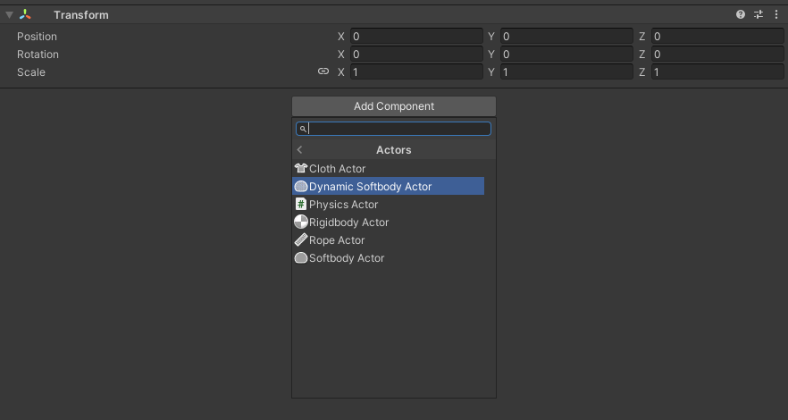
Assign the Simulation Mesh and a Physics World to the DynamicSoftbodyActor component
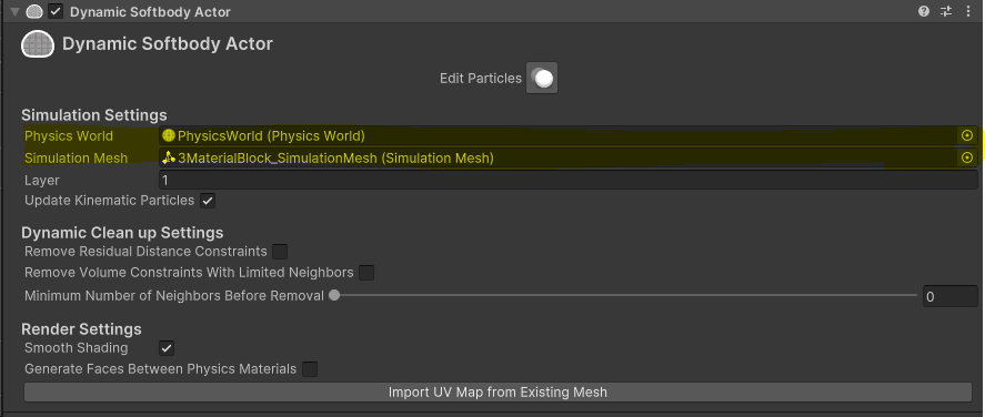
When using the object with Cut/Tear we recommend enabling the Remove Residual Distance Constraints and RemoveVolumeConstraintsWithLimitedNeighbors options. Also the MinimumNumberOfNeighborsBeforeRemoval is recommended to be set to 2. These options will help to remove the constraints that are not needed anymore and reduce visual artifacts while cutting/tearing.
Press Edit Particles in the inspector to edit particles in the Scene view.
Instructions
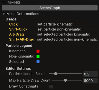
Left click: make particles kinematic.
Shift + left click: make particles non-kinematic.
Alt + drag: marquee-select particles and make them kinematic.
Shift + Alt + drag: marquee-select particles and make them non-kinematic.
Particle Ledger
Red: kinematic.
Green: non-kinematic.
Blue: selected.
Configuration Settings
Particle scale: How big particles are, helping with the visualization.
Particle count: How many particles show. Restricting the number of particles shown can help with performance when editing large meshes.
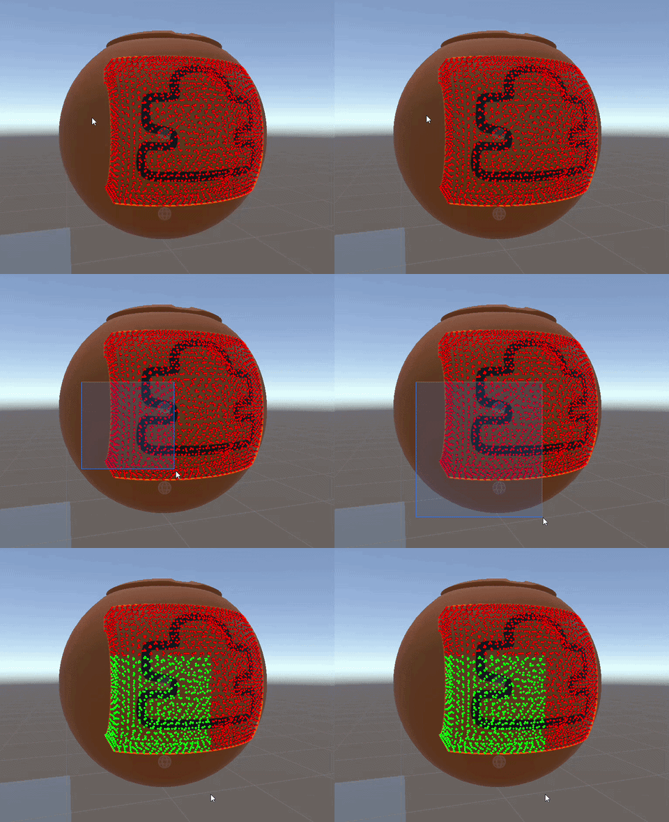
Marquee Selection can help you select multiple particles at once. You can hold the Alt key and drag to marquee-select particles and make them kinematic, or hold Shift + Alt and drag to marquee-select particles and make them non-kinematic.
Render the Dynamic Softbody.
The mesh of the Dynamic softbody is generated based on the current outer surface of the simulation mesh. To render it, you must add a MeshRenderer component to the GameObject and assign one or more Materials to it.
The Render Settings section of the inspector controls how that mesh is built. See Render Settings below.
To give the softbody a proper texture (rather than a flat material), follow the Texturing workflow.
Render Settings
These options live in the Render Settings section of the DynamicSoftbodyActor inspector and control how the per-frame render mesh is generated.
Setting |
Description |
|---|---|
Smooth Shading |
Generate smooth (interpolated) normals instead of flat, hard-edged normals. When UV Storage Mode is Per-Wedge, the geometry is always built flat (per face-corner) so that authored UV seams survive; smooth shading is then applied as a normals-only pass, so you still get smooth lighting. |
Generate Faces Between Physics Materials |
Emit render faces on the boundary between two different physics materials. Useful when the outer material is transparent and you want the material inside it to remain visible. |
Separate Interior Material |
Route the faces exposed by a cut (the cut cross-section) into a dedicated interior submesh, so they can use a separate “inside” material. Assign that material to the last slot of the MeshRenderer; the original outer surface keeps its normal material(s). This adds one extra submesh/material slot. |
UV Storage Mode |
How UVs are stored and read when the render mesh is rebuilt. |
Wedge Coords (.tetuv) |
The per-wedge UV authoring source. Assigning a |
Note
The render mesh only fully populates while the object is simulating (Play mode). Options such as Export to OBJ operate on that runtime mesh.